
Servos constitute a popular building block for many robotics projects. Servos are well known for their “stiff” positioning. Given a command to move to a position, a servo will jerk to that position and hold it no matter how much torque is being applied, up to it’s maximum torque rating.
If we take a look at actuators found in nature such as muscles, we find that this is not the way they work. On the contrary, in almost every living organism the motor control is compliant – it allows for and accommodates perturbations in positioning due to external factors, and it’s reactions are proportional to that. Compliant control allows interaction in the case of environment uncertainty better that stiff, precise control does. Compliant robots exhibit “soft” characteristics that make them safer for interaction.
As most compliant control mechatronic systems are made of specialized components, they are quite pricey and not available to the general public yet. In this post I will outline a simple modification that can be done to cheap hobby servos, which can allow a certain level of compliant control. The gist is to substitute the internal servo control mechanism with an external one using a cheap microcontroller such as an Arduino. The post will cover both hardware and software aspects.
I wasn’t able to find a similar effort by searching on Google. There are of course advanced servo modules such as the Dynamixel series, but the cost of these units makes application prohibitive in projects that require many servos (think: multi-legged robots). I came across the Openservo project which I assume shares similar goals with this post, but it seems the authors have abandoned the project for some time now.
Servo Internals
A basic servo consists of a few components: a geared motor that drives the shaft through a reduction gearbox; a positional encoder such as a potentiometer coupled to the shaft that gives information on the position of the shaft; and a microcontroller that controls the motor according to the actual and desired positions of the shaft. The image below presents a high level outline of the servo internals.
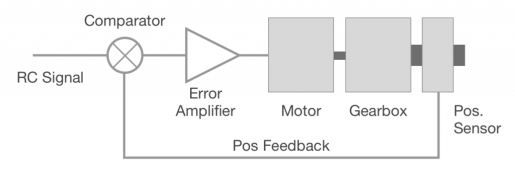
The servo microcontroller takes an input (usually expressed in a special type of PWM) and translates it into a desired angle value. It then checks the angle of the potentiometer to determine the actual angle of the shaft. If there is an error between the desired and actual angles, it activates the motor with the right direction in order to modify the shaft angle and minimize the error.
In most cheap servos the controller essentially behaves like a proportional controller with a very high P value. Once a small angle error is detected, it immediately punches the motor with full current to attempt to eliminate the error. This is in many cases necessary to ensure the accuracy and stiff positioning that servos are known for.
To obtain compliant servo control, we are going to eliminate the built-in servo controller, and feed the angle information and motor control to an external microcontroller such as an Arduino.
Hardware Modifications
Modifying the servo is pretty straightforward. The tiny servo controller has eight leads soldered to it. Two of them go to the motor. Three go to the potentiometer, and another three are the external signal and power input.
To remove the controller, we first need to open the servo case. This is done by removing the four long screws at the bottom side of the servo case. This leaves us with a bottom view of the servo internals, including controller, motor, potentiometer and leads.
Then, we need to snip the two leads to the motor and the three leads to the potentiometer. Alternatively, if you are good with the soldering iron, you can remove the wires from the motor and potentiometer pads, and solder new, longer cables for more convenient connections.
Once done we will need to take the five leads outside the servo casing and close the case. The servo is now ready for microcontroller control.
Hooking up the Servo
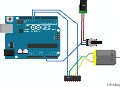
The three leads that connect to the potentiometer will connect to +5V, Analog input and GND, respectively. Make sure it is the wire that you connected to the middle pin of the pot connects to analog. The motor leads connect to the H-Bridge. Schematic is like below:
Microcontroller Script
The script below will read a RC PWM signal on pin 7, the potentiometer position on pin A0 and will output a signal to drive an H-bridge on pins 10 and 11:
// pin 11 -> increase position
// pin 10 -> decrease position

const byte channel_pin = 7;
const byte dec_pin = 10;
const byte inc_pin = 11;

const float p = 1.0;
const float d = 4.0;

int prev_error = 0;

int target = 0;
int c = 50;

void setup() {
  pinMode(channel_pin, INPUT);
  pinMode(dec_pin, OUTPUT);
  pinMode(inc_pin, OUTPUT);
  digitalWrite(inc_pin, HIGH);
  digitalWrite(dec_pin, HIGH);
}

void loop() {
  // Only update target once in a while because it takes
  // a long time to read the RC PWM signal
  if (c>=50)
  {
    target = (2000 - pulseIn(channel_pin, HIGH))/2 + 250;
    c = 0;
  }
  c++;

  // Compute errors, PD terms and reactions
  int ang = analogRead(A0);
  int error = target - ang;
  int react = error * p + (error - prev_error) * d;
  prev_error = error;

  // Apply PWM according to reaction
  if (react > 0)
  {
    // increase
    analogWrite(inc_pin, abs(react));
    digitalWrite(dec_pin, LOW);
  }
  else if (react < 0)
  {
    // decrease
    analogWrite(dec_pin, abs(react));
    digitalWrite(inc_pin, LOW);
  }
  else
  {
    digitalWrite(inc_pin, HIGH);
    digitalWrite(dec_pin, HIGH);
  }
}
It is noteworthy that there is no delay() instruction in the loop. This is because it doesn’t hurt to run the loop as fast as possible. In a scenario where the MCU would have other tasks, adding a delay could help. Also note that I’ve skipped the time term from the derivative calculation. This is a bit sketchy, but I assume that the cycle time is constant.
Testing
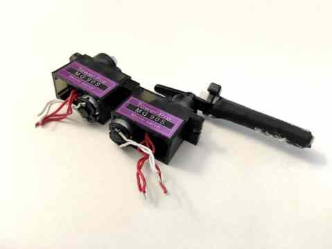
For this test I’m using a ripoff of the popular MG90S metal gear servo. Such ripoffs are usually quite sturdy aluminum gear servos. They are dirt cheap and available at sites such as ebay. Here is an example.
This servo is an ideal candidate for testing the method outlined in this post. The video below demonstrates control using the proposed method vs the internal servo controller:
Conclusion
This post covered modifying cheap servos to have them move smoothly, minimizing stutter and adding customizable control characteristics. With just a bit of effort and easy soldering you can modify any servo to make it compliant like high-end motion control systems offer. This proves useful in projects that by definition interact with the environment, such as multi-legged robots, manipulators etc.
What are your thoughts on this project? Share your experience in the comments below!

You say “Schematic is like below:”, but I don’t see schema. Thanks for helping.
LikeLike
Thanks for pointing out! It is now fixed.
LikeLike
Thank you.
– You say “The script below will read a RC PWM signal on pin 7” but I don’t see anything connected to pin 7 in the schema.
– Why the pin 1 of the L293D is not connected to HIGH level ?
LikeLike
I’ve skipped some connections in the schematic in order to make the diagram easier to read. I’ve since added some labels, hope it reads better.
LikeLike
Much better for understanding ! Thank you.
LikeLike
This is such a great idea for robotic,thank you.
LikeLike
Hi, thanks for the post but could you update the images as none of them seem to load in the browser?
LikeLike
Hey, thanks for the comment! I just updated the images in this post, they should be visible now!
LikeLike